|
32 Camera IP System & Set-Up
This type of system is best suited for factories, office buildings or large business properties. Many large properties may need 32 (or more) cameras in order to cover the areas required. The diagram below is designed to show you how a system could be laid out in a large factory and where the cameras might be mounted. There are different ways this system may be set up as there are a number of PoE switches. The red marks indicate cameras, the blue indicate the PoE switches, the green indicates the Gigabite switches, and yellow for the NVR.
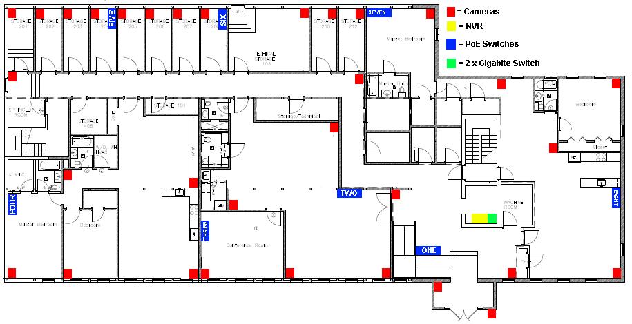
How to set up the System
The above diagram shows the one basic way of setting the system up, however, there are multiple ways to wire this system.
- From the NVR you will need to run two Ethernet cables out to the two Gigabite switches.
- You will need to run an Ethernet cable from one Gigabite switch to the other so that they are both connected in the system.
- Between the two Gigabite switches you will need to run out 8 Ethernet cables to the PoE switches.
- Each of these PoE Switches have 4 non-PoE Ports and 4 PoE Ports.
- From the PoE Ports you need to run 4 ethernet cables out to the camera’s nearest to that switch.
Once this system is all connected up together and linked up. This system should give you stunning 4 Mega Pixel footage and images during both day and night.
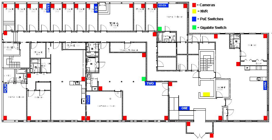
Want to reduce cable lengths?
Another way to connect this system is to move the two Gigabite switches to different locations between the cameras and PoE switches, as shown by the diagram below.
The rest of the system you set up excatly the same as before, but moving the Gigabite switches means you will still have to run four cables back to each PoE switch from the cameras. This means you will only have two cables going back to the NVR from each Gigabite switch. Doing this means you will save on cable length and spend less time laying cable.
Another way to set this system up?
The final option for setting up this system is to connect all the PoE switches together and only use one Gigabite switch, as shown in the diagram below.
To do this, all you have to do is use an ethernet cable to connect each PoE to the other using the non-PoE ports on switches.
For example, to connect PoE 'FIVE', 'SIX', 'SEVEN' and 'EIGHT' together (as labelled below) run an ethernet cable from a non-PoE port in 'FIVE', to a non-PoE port in 'SIX'.

|

